ZHCSH68F November 2017 – February 2024 UCC21220 , UCC21220A
PRODUCTION DATA
- 1
- 1 特性
- 2 应用
- 3 说明
- 4 Device Comparison Table
- 5 Pin Configuration and Functions
-
6 Specifications
- 6.1 Absolute Maximum Ratings
- 6.2 ESD Ratings
- 6.3 Recommended Operating Conditions
- 6.4 Thermal Information
- 6.5 Power Ratings
- 6.6 Insulation Specifications
- 6.7 Safety-Related Certifications
- 6.8 Safety-Limiting Values
- 6.9 Electrical Characteristics
- 6.10 Switching Characteristics
- 6.11 Thermal Derating Curves
- 6.12 Typical Characteristics
- 7 Parameter Measurement Information
- 8 Detailed Description
-
9 Application and Implementation
- 9.1 Application Information
- 9.2
Typical Application
- 9.2.1 Design Requirements
- 9.2.2
Detailed Design Procedure
- 9.2.2.1 Designing INA/INB Input Filter
- 9.2.2.2 Select External Bootstrap Diode and its Series Resistor
- 9.2.2.3 Gate Driver Output Resistor
- 9.2.2.4 Estimating Gate Driver Power Loss
- 9.2.2.5 Estimating Junction Temperature
- 9.2.2.6 Selecting VCCI, VDDA/B Capacitor
- 9.2.2.7 Application Circuits with Output Stage Negative Bias
- 9.2.3 Application Curves
- 10Power Supply Recommendations
- 11Layout
- 12Device and Documentation Support
- 13Revision History
- 14Mechanical, Packaging, and Orderable Information
3 说明
UCC21220 和 UCC21220A 器件是具有 4A 峰值拉电流和 6A 峰值灌电流的基本隔离式和功能隔离式双通道栅极驱动器。它们设计用于在 PFC、隔离式直流/直流和同步整流应用中驱动功率 MOSFET 和 GaNFET,借助超过 100V/ns 的共模瞬态抗扰度 (CMTI),可实现快速开关性能和稳健的接地反弹保护。
这些器件可以配置为两个低侧驱动器、两个高侧驱动器或半桥驱动器。可以将两个输出并联,以形成单个驱动器,由于具有一流的延迟匹配性能,因此可以在重负载条件下使驱动强度加倍。
保护特性包括以下几项:DIS 引脚在设置为高电平时可同时关断两个输出;INA/B 引脚可抑制短于 5ns 的输入瞬态;输入和输出可以承受 –2V 的尖峰达 200ns,所有电源都具有欠压锁定 (UVLO) 功能,有源下拉保护功能可以在断电或悬空时将输出钳制在 2.1V 以下。
凭借这些特性,这些器件可以在各种电源应用中实现高效率、高功率密度和稳健性。
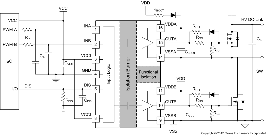
 典型应用
典型应用