ZHCSL04A March 2020 – July 2020 ISO1044
PRODUCTION DATA
- 1 特性
- 2 应用
- 3 说明
- 4 Revision History
- 5 Pin Configuration and Functions
-
6 Specifications
- 6.1 Absolute Maximum Ratings
- 6.2 ESD Ratings
- 6.3 Recommended Operating Conditions
- 6.4 Thermal Information
- 6.5 Power Ratings
- 6.6 Insulation Specifications
- 6.7 Safety-Related Certifications
- 6.8 Safety Limiting Values
- 6.9 Electrical Characteristics - DC Specification
- 6.10 Switching Characteristics
- 6.11 Insulation Characteristics Curves
- 6.12 Typical Characteristics
- 7 Parametric Measurement Information
- 8 Detailed Description
- 9 Application and Implementation
- 10Power Supply Recommendations
- 11Layout
- 12Device and Documentation Support
- 13Mechanical, Packaging, and Orderable Information
8.3.1 CAN Bus States
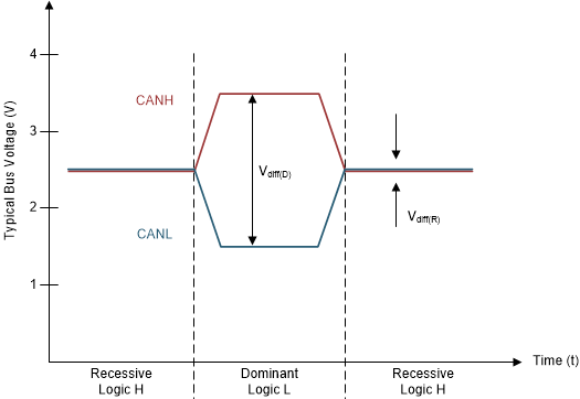
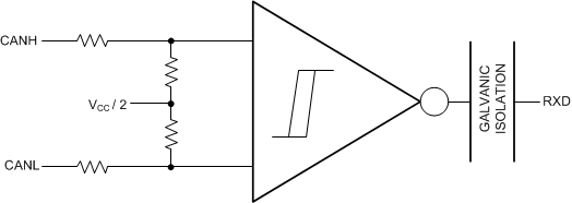
The CAN bus has two states during operation: dominant and recessive. A dominant bus state, equivalent to logic low, is when the bus is driven differentially by a driver. A recessive bus state is when the bus is biased to a common mode of VCC / 2 through the high-resistance internal input resistors of the receiver, equivalent to a logic high. The host microprocessor of the CAN node uses the TXD pin to drive the bus and receives data from the bus on the RXD pin. See Figure 8-1 and Figure 8-2.
 Figure 8-1 Bus States (Physical Bit Representation)
 Figure 8-2 Simplified Recessive Common Mode Bias and Receiver