SLAU298A November 2009 – May 2021
- Trademarks
- 1ADS8555EVM-PDK Overview
- 2EVM Analog Interface
- 3Digital Interface
- 4Power Supplies
- 5Installing the ADS8555EVM Software
-
6ADS8555EVM Operation
- 6.1 Connecting the Hardware and Running the GUI
- 6.2 Jumper Settings for the ADS8555EVM
- 6.3 Modifying Hardware and Using Software to Evaluate Other Devices in the Family
- 6.4 EVM GUI Global Settings for ADC Control and Registers
- 6.5 Time Domain Display
- 6.6 Frequency Domain Display
- 6.7 Histogram Display
- 7Bill of Materials, Layout, and Schematics
- 8Revision History
6.3 Modifying Hardware and Using Software to Evaluate Other Devices in the Family
The ADS8555 is part of a family of related devices. This EVM hardware and software support the entire family because all the devices are pin-for-pin compatible. The Table 6-2 lists other compatible devices in the family. The following procedure shows how to modify the hardware and software to evaluate the other devices in this family.
- Desolder the ADS8555 and replace this device with the device you want to evaluate.
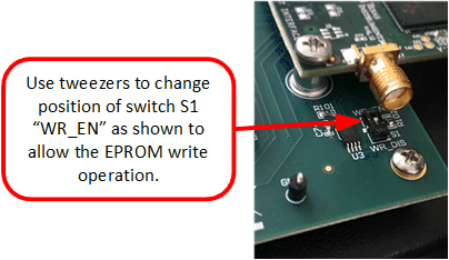
- Enable the EEPROM for writing. This process is done by changing switch S2 to the WR_EN (top) position using tweezers. Figure 6-3 details this process.
- Connect the EVM and start the GUI as described in Figure 6-2.
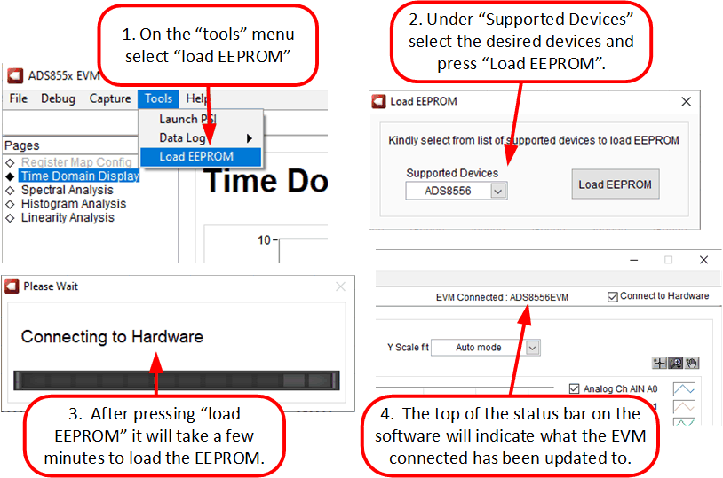
- Under the Tools menu in Figure 6-4, select Load EEPROM to load the EEPROM according to the device that is currently installed. When this procedure is successfully completed, the status bar at the top of the software updates according to the device installed on the hardware.
Table 6-2 Compatible Devices
| DEVICE | RESOLUTION | PARALLEL DATA RATE | SERIAL DATA RATE | OTHER FEATURE |
|---|---|---|---|---|
| ADS8555 | 16 | 630 | 450 | Does not have partial power-down mode |
| ADS8556 | 16 | 630 | 450 | — |
| ADS8557 | 14 | 670 | 470 | — |
| ADS8558 | 12 | 730 | 500 | — |
 Figure 6-3 Enable EEPROM for Writing
 Figure 6-4 Configure EEPROM and Software for
the New Device