SLUAAH1 December 2021 UCC24624
2.3 Dual SR Controllers with Paralleled MOSFETs Configuration
The SR controller has limited capability to drive paralleled MOSFETs at higher switching frequency, due to its packaging and thermal constrain. To improve the thermal management of the SR controller UCC24624, a new structure of using a dual SR controller is proposed.
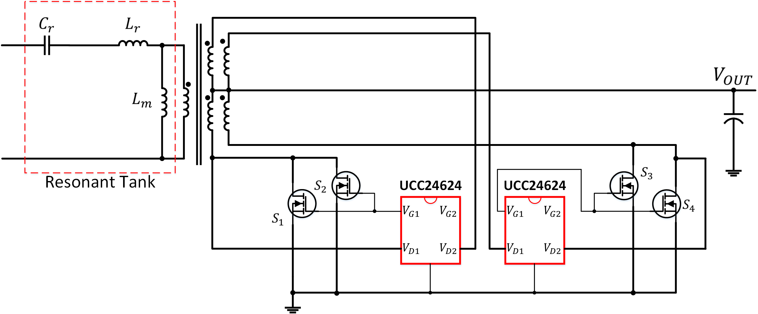
The new structure uses one UCC24624 to drive the SR on each side of a center-tapped transformer. The benefit of this structure is UCC24624 just needs to drive one side of the FETs which could reduce the power dissipation to half. Figure 2-3 shows the proposed structure.
Dual SR controller implementation can effectively divide total driving loss into two separate controllers and it can make each UCC24624 operate within its thermal limit. According to Equation 9, each UCC24624 just needs to handle half of the total driving loss as Equation 11.
Noted, the introduced additional SR controller UCC24624 increases the static power loss. However, it can be neglected comparing with the overall system power level.
 Figure 2-3 Dual UCC24624 Application Schematic